HSRP配置实例加原理一、HSRP原理(Hot Standby Routing protocol) 1、HSRP为IP网络提供了容错和增强的路由选择功能。 2、HSRP备份组由一台活跃的路由器、一台备份路由器、一台虚拟路由器和其他路由器组成。 3、活跃路由器负责转发发动到虚拟路由器的数据包;备份路由器负责监视当活跃路由器不能工作,迅速承担转发数据包的责任;虚拟路由器向最终用户提供一个连续工作的路由器。 4、HSRP组内的路由器通过优先级衡量路由器的优先程度,优先级最高的为活跃路由器。 二、实验拓扑图
实验要求:
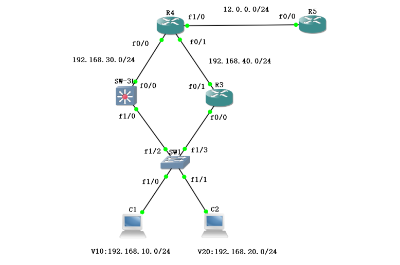
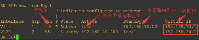
1、三层交换机SW-3L和路由器R3分别为HSRP备份组中的活跃路由器和备份路由器。其中SW-3L为192.168.10.0网段的活跃路由器,R3为192.168.20.0网段的活跃路由器。
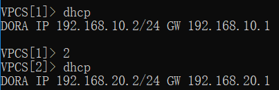
2、SW-3L为C1的DHCP服务器,R3为C2的DHCP的服务器。
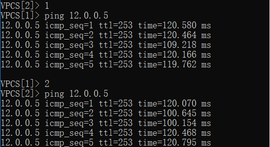
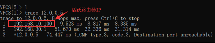
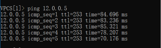
3、C1和C2可以分别访问12.0.0.0网段的公网地址。
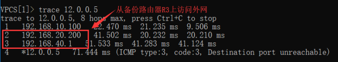
4、手动破环其中一台路由器验证HSRP协议是否生效,并且用trace追踪访问的路径。
三、实验步骤 SW1#conf t SW1(config)#no ip routing //关闭路由功能 SW1(config)#vlan 10,20 //新建vlan SW1(config-vlan)#exit SW1(config)#int f1/0 SW1(config-if)#switchport access vlan 10 //绑定端口 SW1(config-if)#int f1/1 SW1(config-if)#switchport access vlan 20 SW1(config)#int f1/2 SW1(config-if)#switchport mode trunk //将交换机出口设为干道trunk模式 SW1(config-if)#int f1/3 SW1(config-if)#switchport mode trunk 2、配置三层交换机 SW-3L#conf t SW-3L(config)#int f1/0 SW-3L(config-if)#switchport mode trunk //将与交换机相连的端口设为trunk模式 SW-3L(config-if)#exit SW-3L(config)#vlan 10,20 //添加vlan SW-3L(config-vlan)#int vlan 10 SW-3L(config-if)#ip add 192.168.10.100 255.255.255.0 //配置虚拟接口IP SW-3L(config-if)#no shut SW-3L(config-if)#int vlan 20 SW-3L(config-if)#ip add 192.168.20.100 255.255.255.0 SW-3L(config-if)#no shut SW-3L(config-if)#exit SW-3L(config)#int vlan 10 SW-3L(config-if)#standby 1 ip 192.168.10.1 //配置HSRP虚拟路由的IP作为访问的网关 *注:配置虚拟IP地址必须和端口配置的实际地址处于同一网段 SW-3L(config-if)#standby 1 preempt //取得活跃路由器的优先权,默认优先级为100 SW-3L(config-if)#standby 1 track f0/0 //指定上行端口 SW-3L(config-if)#int f0/0 SW-3L(config-if)#ip add 192.168.30.2 255.255.255.0 //配置上行接口IP地址 SW-3L(config-if)#no shut SW-3L(config-if)#int vlan 20 SW-3L(config-if)#standby 2 ip 192.168.20.1 //配置HSRP虚拟路由IP SW-3L(config-if)#standby 2 priority 95 //将对应的优先级设为比R3上活跃路由器低 *注:备份路由组号要与R3上活跃路由组号一致 SW-3L(config-if)#end SW-3L#conf t SW-3L(config)#router ospf 110 //ospf宣告自身网段 SW-3L(config-router)#network 192.168.10.0 0.0.0.255 area 0 SW-3L(config-router)#network 192.168.20.0 0.0.0.255 area 0 SW-3L(config-router)#network 192.168.30.0 0.0.0.255 area 0 SW-3L(config)#ip dhcp pool v10 //配置DHCP服务器 SW-3L(dhcp-config)#network 192.168.10.0 255.255.255.0 SW-3L(dhcp-config)#default-router 192.168.10.1 3、配置R3 R3#conf t R3(config)#int f0/0 R3(config-if)#no shut //开启物理接口 R3(config-if)#int f0/0.10 //进入单臂路由的虚拟接口 R3(config-subif)#encapsulation dot1Q 10 //配置封装协议为vlan10 R3(config-subif)#ip add 192.168.10.200 255.255.255.0 //配置接口真实IP地址 R3(config-subif)#no shut R3(config-subif)#int f0/0.20 R3(config-subif)#encapsulation dot1Q 20 //同上 R3(config-subif)#ip add 192.168.20.200 255.255.255.0 R3(config-subif)#no shut R3(config-subif)#int f0/0.10 R3(config-subif)#standby 1 ip 192.168.10.1 //配置HSRP虚拟路由IP R3(config-subif)#standby 1 priority 95 //将对应的优先级设为比SW-3L上活跃路由器低 *注:HSRP组号与SW-3L上一致 R3(config-subif)#int f0/0.20 R3(config-subif)#standby 2 ip 192.168.20.1 //配置HSRP虚拟路由器IP R3(config-subif)#standby 2 preempt //取得活跃路由器的优先权,默认优先级为100 *注:配置虚拟IP地址必须和端口配置的实际地址处于同一网段 R3(config-subif)#standby 2 track f0/1 //指定上行接口 R3(config-subif)#exit R3(config)#int f0/1 R3(config-if)#ip add 192.168.40.2 255.255.255.0 //配置上行接口IP地址 R3(config-if)#no shut R3(config-if)#exit R3(config)#router ospf 110 //ospf宣告自身网段 R3(config-router)#network 192.168.10.0 0.0.0.255 area 0 R3(config-router)#network 192.168.20.0 0.0.0.255 area 0 R3(config-router)#network 192.168.40.0 0.0.0.255 area 0 R3(config)#ip dhcp pool v20 //配置C2的DHCP服务器 R3(dhcp-config)#network 192.168.20.0 255.255.255.0 R3(dhcp-config)#default-router 192.168.20.1 4、配置R4
R4#conf t
R4(config)#int f0/0     //配置对应网段的IP地址
R4(config-if)#ip add 192.168.30.1 255.255.255.0
R4(config-if)#no shut
R4(config-if)#int f0/1
R4(config-if)#ip add 192.168.40.1 255.255.255.0
R4(config-if)#no shut
R4(config-if)#int f1/0
R4(config-if)#ip add 12.0.0.1 255.255.255.0     //配置外网口IP地址
R4(config-if)#no shut
R4(config)#router ospf 110      //ospf宣告自身相连的网段
R4(config-router)#network 12.0.0.0 0.0.0.255 area 0
R4(config-router)#network 192.168.30.0 0.0.0.255 area 0
R4(config-router)#network 192.168.40.0 0.0.0.255 area 0
    5、配置外网路由器R5
R5(config)#int f0/0     //配置端口IP
R5(config-if)#ip add 12.0.0.5 255.255.255.0
R5(config-if)#no shut
R5(config)#router ospf 110  //osfp宣告自身IP
R5(config-router)#network 12.0.0.0 0.0.0.255 area 0
四、验证实验 (责任编辑:IT) |